Load Balancer
We previously introduced how to build a cluster of instances in the Service Cluster topic. In this lecture, we’ll explore how to expose a service to the outside world.
Load Balancer
Reverse Proxy Pattern
When running a cluster of service instances, the instances typically reside on different machines with distinct addresses. Moreover, instances can be dynamically added or removed. As a result, it is impractical for clients to communicate directly with individual service instances.
A Reverse Proxy is a pattern that exposes a system through a single entry point while concealing its underlying internal structure. Following this pattern, service instances are placed behind a proxy that forwards traffic to them. The proxy should have a fixed and discoverable endpoint, often provided through DNS.
Load Balancing
Proxying alone isn’t enough. To utilize resources efficiently, we want to distribute traffic evenly across the service instances.
For example, one instance might be handling 4 requests while another is processing only 1, creating a clear imbalance.
To solve this problem, we add load balancing capabilities to the proxy component, which we refer to as a Load Balancer . For example, the load balancer can distribute traffic evenly across the cluster.
Service Discovery
A Load Balancer needs to know which service instances are available behind it. The most common approach is to implement a central Service Discovery system that tracks all available instances.
In this setup, service instances must register themselves with the Load Balancer , which would otherwise have no inherent knowledge of their existence.
Health Check
To ensure that only healthy instances receive traffic, the Load Balancer periodically performs health checks and removes unhealthy instances from the pool.
Load Balancing Algorithms
Several algorithms can be used to select a service instance from a cluster.
Round-robin
The Round-robin algorithm is one of the most common algorithms and is often the default option in many load balancing solutions. It cycles through the list of instances in order, assigning each new request to the next instance in the sequence.
This method works well for short-lived requests of similar size, such as HTTP requests.
However, problems can arise when workloads vary significantly.
For example, if Instance 2 is already overwhelmed with ongoing requests, the load balancer will still continue sending it new requests when its turn arrives, even while other instances remain underutilized.
Least Connections
The Least Connections algorithm selects the instance currently handling the fewest active connections. This requires the load balancer to track the number of in-flight requests on each instance.
Is this better than Round-robin?
Not necessarily, because the number of active connections does not always reflect actual resource consumption.
For example, 10 requests on Instance 1 might use only 1 MB of memory, while 3 requests on Instance 2 could consume 100 MB.
This strategy is particularly effective for long-lived sessions, such as WebSocket , where client sessions remain connected to the same server for extended periods. In such cases, Round-robin can easily produce an imbalance, making Least Connections a more suitable choice.
Session Stickiness
Load balancing algorithms typically determine which server should handle each request. However, this behavior can be overridden using a feature called Session Stickiness.
When a client first connects, the load balancer assigns a stickiness key and returns it in the response:
- The client stores the key locally.
- For subsequent requests, the client includes the key, ensuring that it connects to the same instance.
Why is this used?
In many load balancing solutions, this feature is disabled by default. However, for stateful applications, such as multiplayer games or chat services, clients often need to interact consistently with the same server instance. One example is reconnecting to the same session after a temporary disconnection.
However, this behavior comes at a cost. Session Stickiness can easily lead to uneven load distribution because it overrides the load balancer’s configured algorithm in favor of routing a client to a specific instance.
Load Balancer Types
There are two common types of Load Balancer : Layer 4 Load Balancer and Layer 7 Load Balancer . They differ in the network layer at which load balancing occurs.
OSI Review
A network message’s journey through a machine can be described using the 7 layers of the OSI model.
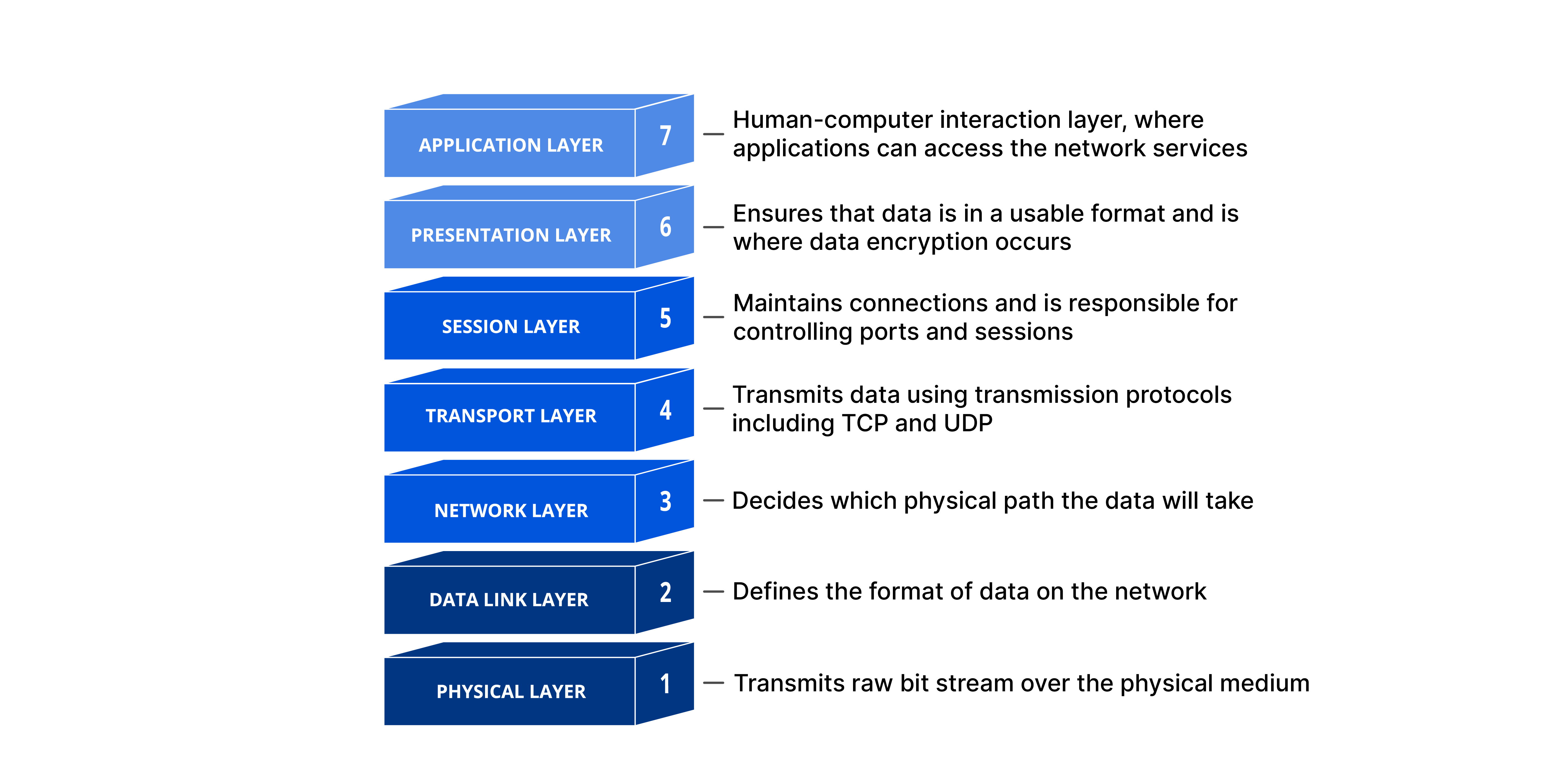
This layered design helps separate concerns. Each layer has distinct responsibilities, operates independently, and can evolve autonomously. In this topic, we’ll focus solely on the Application, Transport, and Network layers.
Encapsulation
When a process sends a message to another machine, the message is progressively encapsulated, transforming from application data into a network message:
- Application Layer (L7): The application formats the message according to its specific protocol, such as HTTP.
- Transport Layer (L4): The machine attaches the port number to the message.
- Network Layer (L3): The machine adds its address to the message.
As the message moves downward through the layers, it is enriched with additional networking information at each stage. Notably, lower layers cannot interpret or modify the data encapsulated by higher layers.
Decapsulation
On the recipient side, the message undergoes decapsulation, moving upward through the layers:
- Network Layer (L3): Reads and strips off the address.
- Transport Layer (L4): Reads the port number and routes the message to the correct application.
- Application Layer (L7): Interprets and processes the protocol-specific message.
Layer 7 Load Balancer
A Layer 7 Load Balancer operates at the Application Layer (L7) of the OSI model, handling protocols such as HTTP and WebSocket .
Operating at this higher layer allows it to inspect application-specific details, such as HTTP headers, parameters, and message bodies, enabling more intelligent routing decisions.
Technically, two separate connections are established:
- Between the client and the load balancer.
- Between the load balancer and the service.
API Gateway Pattern
API Gateway is a design pattern that provides a single entry point to a system’s public services.
It can also provide load-balancing capabilities, allowing multiple services to share the same infrastructure while using routing rules to direct traffic based on criteria such as the domain, HTTP path, headers, or query parameters.
For example:
- Requests to
/aare routed toService A. - Requests to
/bare routed toService B.
SSL Termination
A major challenge with Layer 7 Load Balancer is handling traffic encrypted with SSL/TLS. Because Layer 7 Load Balancer needs to inspect application-level data to make routing decisions, it cannot operate directly on end-to-end encrypted traffic.
In other words, we cannot use a Layer 7 Load Balancer while preserving complete end-to-end encryption. To make L7 load balancing possible, SSL/TLS decryption must instead occur at the Load Balancer itself. This process is known as SSL Termination .
New connections are then established internally to forward plaintext traffic to the services.
Security Concern
This introduces a security risk because decrypted data resides at the load balancer, potentially exposing sensitive information.
In some compliance and data governance contexts, data must remain encrypted all the way to its destination service. Additionally, using an external load balancing service for SSL Termination may expose decrypted data outside the trusted environment.
Layer 4 Load Balancer
A Layer 4 Load Balancer operates at the Transport Layer (L4) of the OSI model. It cannot inspect application-level content, so routing decisions are based solely on the destination address and port.
Essentially, a Layer 4 Load Balancer acts like a network router between clients and services. Once a client connects to a server, it continues communicating with the same instance for as long as the connection remains open. This behavior arises from packet segmentation, where large messages are split into multiple network packets, also known as TCP segments.
For example, an HTTP request may be split into two network segments. A Layer 7 Load Balancer understands application protocols such as HTTP and can route requests to the appropriate targets.
Conversely, a Layer 4 Load Balancer is unaware of application-level protocols and may accidentally distribute segments of the same request across different servers, resulting in errors.
The solution is to forward all segments belonging to the same connection to the same server until the connection is closed.
Why choose a Layer 4 Load Balancer over a Layer 7 Load Balancer ?
- It avoids SSL Termination , which can introduce security risks.
- It provides significantly better performance because it can simply forward packets without interpreting application-level content.
However, because of this connection stickiness, a Layer 4 Load Balancer can easily become unbalanced: one server might receive a disproportionate amount of traffic while others remain underutilized. Still, it is a solid choice for stateful, high-performance services such as multiplayer gaming backends.